Halcon一维测量官方案例解析
下面的例子简要介绍了如何使用HALCON的一维测量工具。最长的部分是预处理和后处理;测量本身只包括两个操作符调用。
测量保险丝-fuse
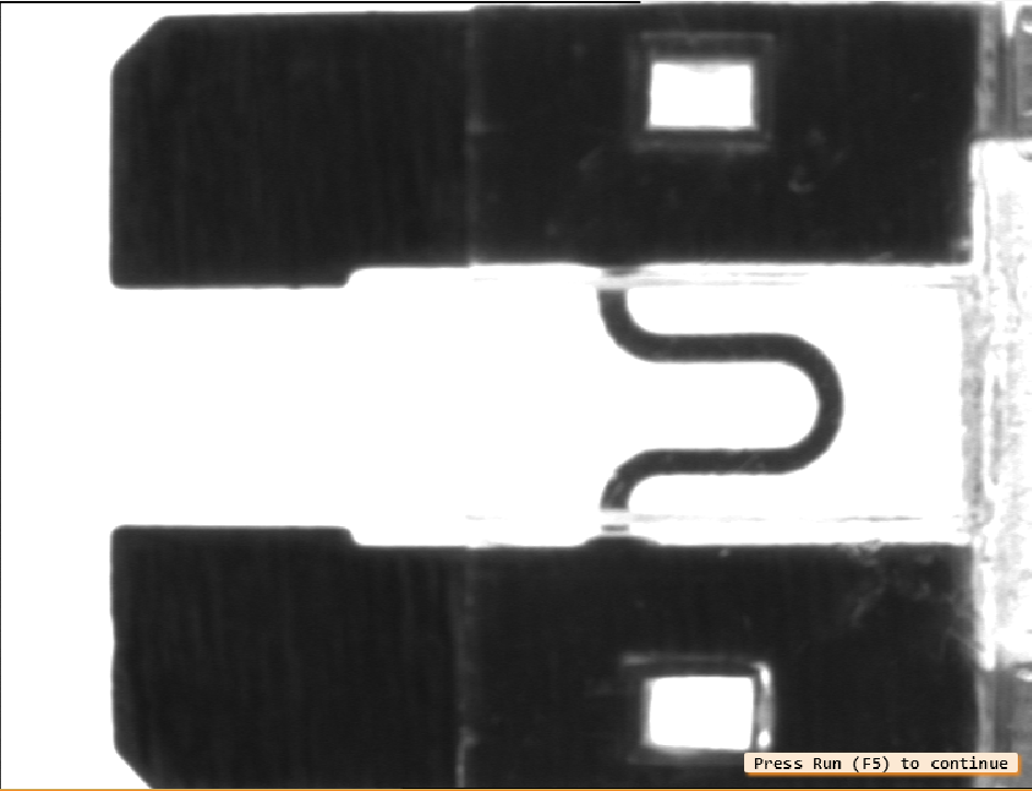
预处理主要是测量线的生成。在示例程序中,这个步骤是通过将测量对象的参数分配给变量来完成的。
read_image (Fuse, 'fuse')
Row := 297
Column := 545
Length1 := 80
Length2 := 10
Angle := rad(90)
gen_rectangle2 (ROI, Row, Column, Angle, Length1, Length2)
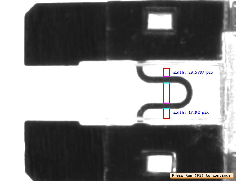
现在通过将测量对象应用到图像上进行实际测量。参数的选择使得暗区周围的边缘被分为两组线段,结果返回边缘的位置和两组线段的宽度和距离。
measure_pairs (Fuse, MeasureHandle, 1, 1, 'negative', 'all', RowEdgeFirst, ColumnEdgeFirst, AmplitudeFirst, RowEdgeSecond, ColumnEdgeSecond, AmplitudeSecond, IntraDistance, InterDistance)

最后生成一个带有测量线参数的区域,并将边缘位置转换为短XLD等值线来显示结果。
for i := 0 to |RowEdgeFirst| - 1 by 1
    gen_contour_polygon_xld (EdgeFirst, [-sin(Angle + rad(90)) * Length2 + RowEdgeFirst[i],-sin(Angle - rad(90)) * Length2 + RowEdgeFirst[i]], [cos(Angle + rad(90)) * Length2 + ColumnEdgeFirst[i],cos(Angle - rad(90)) * Length2 + ColumnEdgeFirst[i]])
    gen_contour_polygon_xld (EdgeSecond, [-sin(Angle + rad(90)) * Length2 + RowEdgeSecond[i],-sin(Angle - rad(90)) * Length2 + RowEdgeSecond[i]], [cos(Angle + rad(90)) * Length2 + ColumnEdgeSecond[i],cos(Angle - rad(90)) * Length2 + ColumnEdgeSecond[i]])
    dev_set_color ('cyan')
    dev_display (EdgeFirst)
    dev_set_color ('magenta')
    dev_display (EdgeSecond)
    dev_set_color ('blue')
    if (i == 0)
        set_tposition (WindowID, RowEdgeFirst[i] + 5, ColumnEdgeFirst[i] + 20)
    else
        set_tposition (WindowID, RowEdgeFirst[i] - 40, ColumnEdgeFirst[i] + 20)
    endif
    write_string (WindowID, 'width: ' + IntraDistance[i] + ' pix')
endfor
源程序
* fuse.hdev: 测量保险丝的宽度
*
dev_update_window ('off')
dev_close_window ()
* ****
* 采集图像
* ****
read_image (Fuse, 'fuse')
get_image_size (Fuse, Width, Height)
dev_open_window_fit_image (Fuse, 0, 0, Width, Height, WindowID)
set_display_font (WindowID, 12, 'mono', 'true', 'false')
dev_set_draw ('margin')
dev_set_line_width (3)
dev_display (Fuse)
set_display_font (WindowID, 12, 'mono', 'true', 'false')
disp_continue_message (WindowID, 'black', 'true')
stop ()
* ****
* 创建测量对象
* ****
* -> specify ROI
Row := 297
Column := 545
Length1 := 80
Length2 := 10
Angle := rad(90)
gen_rectangle2 (ROI, Row, Column, Angle, Length1, Length2)
* -> create measure object
gen_measure_rectangle2 (Row, Column, Angle, Length1, Length2, Width, Height, 'bilinear', MeasureHandle)
dev_display (ROI)
disp_continue_message (WindowID, 'black', 'true')
stop ()
* ****
* 测量
* ****
measure_pairs (Fuse, MeasureHandle, 1, 1, 'negative', 'all', RowEdgeFirst, ColumnEdgeFirst, AmplitudeFirst, RowEdgeSecond, ColumnEdgeSecond, AmplitudeSecond, IntraDistance, InterDistance)
disp_continue_message (WindowID, 'black', 'true')
stop ()
* ****
* 结果可视化
* ****
for i := 0 to |RowEdgeFirst| - 1 by 1
    gen_contour_polygon_xld (EdgeFirst, [-sin(Angle + rad(90)) * Length2 + RowEdgeFirst[i],-sin(Angle - rad(90)) * Length2 + RowEdgeFirst[i]], [cos(Angle + rad(90)) * Length2 + ColumnEdgeFirst[i],cos(Angle - rad(90)) * Length2 + ColumnEdgeFirst[i]])
    gen_contour_polygon_xld (EdgeSecond, [-sin(Angle + rad(90)) * Length2 + RowEdgeSecond[i],-sin(Angle - rad(90)) * Length2 + RowEdgeSecond[i]], [cos(Angle + rad(90)) * Length2 + ColumnEdgeSecond[i],cos(Angle - rad(90)) * Length2 + ColumnEdgeSecond[i]])
    dev_set_color ('cyan')
    dev_display (EdgeFirst)
    dev_set_color ('magenta')
    dev_display (EdgeSecond)
    dev_set_color ('blue')
    if (i == 0)
        set_tposition (WindowID, RowEdgeFirst[i] + 5, ColumnEdgeFirst[i] + 20)
    else
        set_tposition (WindowID, RowEdgeFirst[i] - 40, ColumnEdgeFirst[i] + 20)
    endif
    write_string (WindowID, 'width: ' + IntraDistance[i] + ' pix')
endfor
disp_continue_message (WindowID, 'black', 'true')
stop ()
* ****
* 销毁对象
* ****
close_measure (MeasureHandle)
dev_update_window ('on')
dev_clear_window ()
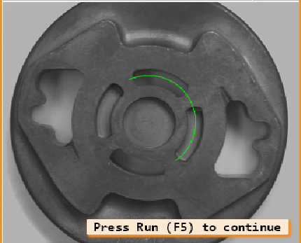
测量金属铸造部件-measure_arc
本例是检测铸件倒角后拉长孔之间的距离。为了达到最好的精度,建议使用背光与远心镜头相结合的方式,而不是图中的设置。

这个任务可以通过使用带有圆形测量ROI的测量工具轻松解决。ROI的中心被放置在铸件的中心;半径设置为拉长孔与中心的距离。
Row := 275
Column := 335
Radius := 107
AngleStart := -rad(55)
AngleExtent := rad(170)
gen_measure_arc (Row, Column, Radius, AngleStart, AngleExtent, 10, Width, Height, 'nearest_neighbor', MeasureHandle)
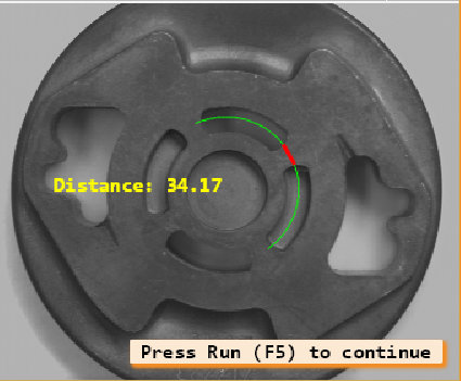
现在,可以通过一个运算符的调用来测量孔之间的距离。
measure_pos (Zeiss1, MeasureHandle, 1, 10, 'all', 'all', RowEdge, ColumnEdge, Amplitude, Distance)
源程序
* 例子包括很多可视化操作。
read_image (Zeiss1, 'zeiss1')
get_image_size (Zeiss1, Width, Height)
dev_close_window ()
dev_open_window (0, 0, Width / 2, Height / 2, 'black', WindowHandle)
set_display_font (WindowHandle, 14, 'mono', 'true', 'false')
dev_display (Zeiss1)
disp_continue_message (WindowHandle, 'black', 'true')
stop ()
* draw_circle (WindowHandle, Row, Column, Radius)
Row := 275
Column := 335
Radius := 107
AngleStart := -rad(55)
AngleExtent := rad(170)
dev_set_draw ('fill')
dev_set_color ('green')
dev_set_line_width (1)
get_points_ellipse (AngleStart + AngleExtent, Row, Column, 0, Radius, Radius, RowPoint, ColPoint)
disp_arc (WindowHandle, Row, Column, AngleExtent, RowPoint, ColPoint)
dev_set_line_width (3)
gen_measure_arc (Row, Column, Radius, AngleStart, AngleExtent, 10, Width, Height, 'nearest_neighbor', MeasureHandle)
disp_continue_message (WindowHandle, 'black', 'true')
stop ()
count_seconds (Seconds1)
n := 10
for i := 1 to n by 1
    measure_pos (Zeiss1, MeasureHandle, 1, 10, 'all', 'all', RowEdge, ColumnEdge, Amplitude, Distance)
endfor
count_seconds (Seconds2)
Time := (Seconds2 - Seconds1) / n
disp_continue_message (WindowHandle, 'black', 'true')
* stop ()
distance_pp (RowEdge[1], ColumnEdge[1], RowEdge[2], ColumnEdge[2], IntermedDist)
* dev_display (Zeiss1)
dev_set_color ('red')
* disp_circle (WindowHandle, RowEdge, ColumnEdge, RowEdge - RowEdge + 1)
disp_line (WindowHandle, RowEdge[1], ColumnEdge[1], RowEdge[2], ColumnEdge[2])
dev_set_color ('yellow')
disp_message (WindowHandle, 'Distance: ' + IntermedDist, 'image', 250, 80, 'yellow', 'false')
* dump_window (WindowHandle, 'tiff_rgb', 'C:\\Temp\\zeiss_result')
dev_set_line_width (1)
* disp_continue_message (WindowHandle, 'black', 'true')
stop ()
dev_clear_window ()
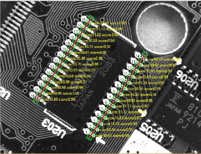
使用模糊测量法测量集成电路-fuzzy_measure_pin
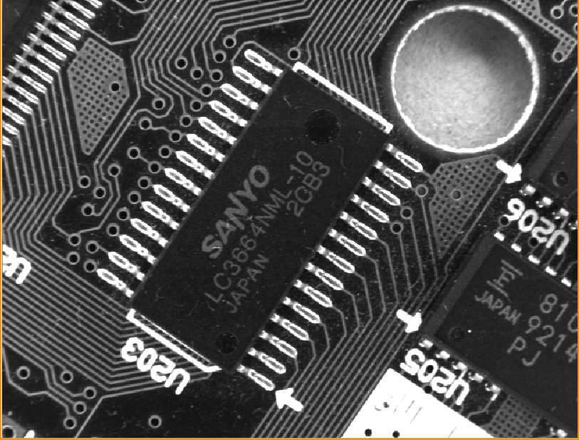
本例是测量IC的引线宽度和引线距离。本例中的照明条件相当困难,造成了每个引线都有四个边缘可见。模糊规则就是用于将测量限制在正确的(外)引线上。
gen_measure_rectangle2 (Row2, Col2, Phi2, Length1, Length2, Width, Height, 'nearest_neighbor', MeasureHandle2)
create_funct_1d_pairs ([0.0,0.3], [1.0,0.0], FuzzyAbsSizeDiffFunction)
set_fuzzy_measure_norm_pair (MeasureHandle1, 11.0, 'size_abs_diff', FuzzyAbsSizeDiffFunction)
fuzzy_measure_pairs (Image, MeasureHandle1, 1, 30, 0.5, 'positive', RowEdgeFirst1, ColumnEdgeFirst1, AmplitudeFirst1, RowEdgeSecond1, ColumnEdgeSecond1, AmplitudeSecond1, RowEdgeMiddle1, ColumnEdgeMiddle1, FuzzyScore1, IntraDistance1, InterDistance1)
源程序
dev_close_window ()
read_image (Image, 'board/board-06')
get_image_size (Image, Width, Height)
dev_open_window (0, 0, Width, Height, 'black', WindowHandle)
*
* 模糊测量:
Row1 := 305.5
Col1 := 375.5
Phi1 := 0.982
Length1 := 167
Length2 := 8
gen_measure_rectangle2 (Row1, Col1, Phi1, Length1, Length2, Width, Height, 'nearest_neighbor', MeasureHandle1)
Row2 := 188.5
Col2 := 202.5
Phi2 := Phi1 - rad(180)
gen_measure_rectangle2 (Row2, Col2, Phi2, Length1, Length2, Width, Height, 'nearest_neighbor', MeasureHandle2)
* 创建一个模糊函数来选择芯片引脚边缘对的大小(约11Pixels)。
create_funct_1d_pairs ([0.0,0.3], [1.0,0.0], FuzzyAbsSizeDiffFunction)
set_fuzzy_measure_norm_pair (MeasureHandle1, 11.0, 'size_abs_diff', FuzzyAbsSizeDiffFunction)
set_fuzzy_measure_norm_pair (MeasureHandle2, 11.0, 'size_abs_diff', FuzzyAbsSizeDiffFunction)
fuzzy_measure_pairs (Image, MeasureHandle1, 1, 30, 0.5, 'positive', RowEdgeFirst1, ColumnEdgeFirst1, AmplitudeFirst1, RowEdgeSecond1, ColumnEdgeSecond1, AmplitudeSecond1, RowEdgeMiddle1, ColumnEdgeMiddle1, FuzzyScore1, IntraDistance1, InterDistance1)
fuzzy_measure_pairs (Image, MeasureHandle2, 1, 30, 0.5, 'positive', RowEdgeFirst2, ColumnEdgeFirst2, AmplitudeFirst2, RowEdgeSecond2, ColumnEdgeSecond2, AmplitudeSecond2, RowEdgeMiddle2, ColumnEdgeMiddle2, FuzzyScore2, IntraDistance2, InterDistance2)
*
* 可视化:
dev_display (Image)
* 可视化测量区域
dev_display_measure_object (Row1, Col1, Phi1, Length1, Length2)
dev_display_measure_object (Row2, Col2, Phi2, Length1, Length2)
* 可视化边缘对
dev_set_draw ('fill')
Pin := 1
dev_display_profile_points ([RowEdgeFirst1,RowEdgeSecond1], [ColumnEdgeFirst1,ColumnEdgeSecond1], Row1, Col1, Phi1, Length1, Length2)
for I := 0 to |ColumnEdgeFirst1| - 1 by 1
    disp_message (WindowHandle, 'size:' + IntraDistance1[I]$'.2f' + ' score:' + FuzzyScore1[I]$'.2f', 'image', RowEdgeSecond1[I], ColumnEdgeSecond1[I] + 10, 'yellow', 'false')
    MRow := RowEdgeSecond1[I] - 5
    MCol := ColumnEdgeSecond1[I] - 20
    dev_set_color ('white')
    gen_circle (Circle, MRow, MCol, 10)
    dev_display (Circle)
    get_string_extents (WindowHandle, Pin, Ascent, Descent, SWidth, SHeight)
    disp_message (WindowHandle, Pin, 'window', MRow - SHeight / 2, MCol - SWidth / 2, 'black', 'false')
    Pin := Pin + 1
endfor
dev_display_profile_points ([RowEdgeFirst2,RowEdgeSecond2], [ColumnEdgeFirst2,ColumnEdgeSecond2], Row2, Col2, Phi2, Length1, Length2)
for I := 0 to |ColumnEdgeFirst2| - 1 by 1
    dev_set_color ('yellow')
    disp_message (WindowHandle, 'size:' + IntraDistance2[I]$'.2f' + ' score:' + FuzzyScore2[I]$'.2f', 'image', RowEdgeFirst2[I], ColumnEdgeFirst2[I] + 10, 'yellow', 'false')
    MRow := RowEdgeFirst2[I] - 5
    MCol := ColumnEdgeFirst2[I] - 20
    dev_set_color ('white')
    gen_circle (Circle, MRow, MCol, 10)
    dev_display (Circle)
    get_string_extents (WindowHandle, Pin, Ascent, Descent, SWidth, SHeight)
    disp_message (WindowHandle, Pin, 'window', MRow - SHeight / 2, MCol - SWidth / 2, 'black', 'false')
    Pin := Pin + 1
endfor
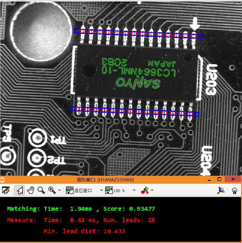
测量可移动的IC的引线-pm_measure_board
本例的任务是测量可移动的芯片引线的位置。 由于芯片可以出现在不同的位置和角度,用于测量的感兴趣的区域必须对齐。
在这种情况下,通过使用基于形状的匹配搜索芯片上的印刷字符来实现对准。
gen_rectangle2 (Rectangle2, Row + Rect2Row, Column + Rect2Col, RectPhi, RectLength1, RectLength2)
reduce_domain (Image, Rectangle, ImageReduced)
create_shape_model (ImageReduced, 4, 0, rad(360), rad(1), 'none', 'use_polarity', 30, 10, ModelID)
找到印刷品后,ROI的位置将相对于印刷字符的位置进行几何变换。
find_shape_model (ImageCheck, ModelID, 0, rad(360), 0.7, 1, 0.5, 'least_squares', 4, 0.7, RowCheck, ColumnCheck, AngleCheck, Score)
hom_mat2d_identity (HomMat2DIdentity)
hom_mat2d_translate (HomMat2DIdentity, RowCheck, ColumnCheck, HomMat2DTranslate)
hom_mat2d_rotate (HomMat2DTranslate, AngleCheck, RowCheck, ColumnCheck, HomMat2DRotate)
affine_trans_pixel (HomMat2DRotate, Rect1Row, Rect1Col, Rect1RowCheck, Rect1ColCheck)

然后,创建测量工具并应用测量。
gen_measure_rectangle2 (Rect1RowCheck, Rect1ColCheck, AngleCheck, RectLength1, RectLength2, Width, Height, 'bilinear', MeasureHandle1)
measure_pairs (ImageCheck, MeasureHandle1, 2, 90, 'positive', 'all', RowEdgeFirst1, ColumnEdgeFirst1, AmplitudeFirst1, RowEdgeSecond1, ColumnEdgeSecond1, AmplitudeSecond1, IntraDistance1, InterDistance1)
源程序
* 这个示例程序展示了如何使用模式匹配与形状模型来定位一个对象。 此外,它还展示了如何使用检测到的物体位置和旋转来构建检测任务的ROI。在这个例子中,IC上的印刷字符被用来寻找IC。 从找到的位置和旋转,构建两个测量矩形来测量IC引线之间的间距。 由于打光的缘故,引线在几个位置和旋转处的饱和灰度值为255,这扩大了引线的实际宽度,减小了引线之间的间距。
dev_update_pc ('off')
dev_update_window ('off')
dev_update_var ('off')
open_framegrabber ('File', 1, 1, 0, 0, 0, 0, 'default', -1, 'default', -1, 'default', 'board/board.seq', 'default', -1, 1, FGHandle)
grab_image (Image, FGHandle)
get_image_size (Image, Width, Height)
dev_close_window ()
dev_open_window (0, 0, Width, Height, 'black', WindowHandle)
dev_open_window (Height + 70, 0, Width, 120, 'black', WindowHandleText)
dev_set_window (WindowHandle)
set_display_font (WindowHandle, 16, 'mono', 'true', 'false')
set_display_font (WindowHandleText, 16, 'mono', 'true', 'false')
dev_set_color ('red')
dev_display (Image)
Row1 := 188
Column1 := 182
Row2 := 298
Column2 := 412
gen_rectangle1 (Rectangle, Row1, Column1, Row2, Column2)
area_center (Rectangle, Area, Row, Column)
Rect1Row := -102
Rect1Col := 5
Rect2Row := 107
Rect2Col := 5
RectPhi := 0
RectLength1 := 170
RectLength2 := 5
gen_rectangle2 (Rectangle1, Row + Rect1Row, Column + Rect1Col, RectPhi, RectLength1, RectLength2)
gen_rectangle2 (Rectangle2, Row + Rect2Row, Column + Rect2Col, RectPhi, RectLength1, RectLength2)
reduce_domain (Image, Rectangle, ImageReduced)
create_shape_model (ImageReduced, 4, 0, rad(360), rad(1), 'none', 'use_polarity', 30, 10, ModelID)
get_shape_model_contours (ShapeModel, ModelID, 1)
hom_mat2d_identity (HomMat2DIdentity)
hom_mat2d_translate (HomMat2DIdentity, Row, Column, HomMat2DTranslate)
affine_trans_contour_xld (ShapeModel, ShapeModelTrans, HomMat2DTranslate)
dev_display (Image)
dev_set_color ('green')
dev_display (ShapeModelTrans)
dev_set_color ('blue')
dev_set_draw ('margin')
dev_set_line_width (3)
dev_display (Rectangle1)
dev_display (Rectangle2)
dev_set_draw ('fill')
dev_set_line_width (1)
dev_set_color ('yellow')
disp_message (WindowHandle, ['Press left button to start','and stop the demo'], 'window', 12, 12, 'black', 'true')
get_mbutton (WindowHandle, Row3, Column3, Button1)
wait_seconds (0.5)
Button := 0
while (Button != 1)
    dev_set_window (WindowHandle)
    dev_set_part (0, 0, Height - 1, Width - 1)
    grab_image (ImageCheck, FGHandle)
    dev_display (ImageCheck)
    count_seconds (S1)
    find_shape_model (ImageCheck, ModelID, 0, rad(360), 0.7, 1, 0.5, 'least_squares', 4, 0.7, RowCheck, ColumnCheck, AngleCheck, Score)
    count_seconds (S2)
    dev_display (ImageCheck)
    if (|Score| > 0)
        dev_set_color ('green')
        hom_mat2d_identity (HomMat2DIdentity)
        hom_mat2d_translate (HomMat2DIdentity, RowCheck, ColumnCheck, HomMat2DTranslate)
        hom_mat2d_rotate (HomMat2DTranslate, AngleCheck, RowCheck, ColumnCheck, HomMat2DRotate)
        affine_trans_contour_xld (ShapeModel, ShapeModelTrans, HomMat2DRotate)
        dev_display (ShapeModelTrans)
        affine_trans_pixel (HomMat2DRotate, Rect1Row, Rect1Col, Rect1RowCheck, Rect1ColCheck)
        affine_trans_pixel (HomMat2DRotate, Rect2Row, Rect2Col, Rect2RowCheck, Rect2ColCheck)
        gen_rectangle2 (Rectangle1Check, Rect1RowCheck, Rect1ColCheck, AngleCheck, RectLength1, RectLength2)
        gen_rectangle2 (Rectangle2Check, Rect2RowCheck, Rect2ColCheck, AngleCheck, RectLength1, RectLength2)
        dev_set_color ('blue')
        dev_set_draw ('margin')
        dev_set_line_width (3)
        dev_display (Rectangle1Check)
        dev_display (Rectangle2Check)
        dev_set_draw ('fill')
        count_seconds (S3)
        gen_measure_rectangle2 (Rect1RowCheck, Rect1ColCheck, AngleCheck, RectLength1, RectLength2, Width, Height, 'bilinear', MeasureHandle1)
        gen_measure_rectangle2 (Rect2RowCheck, Rect2ColCheck, AngleCheck, RectLength1, RectLength2, Width, Height, 'bilinear', MeasureHandle2)
        measure_pairs (ImageCheck, MeasureHandle1, 2, 90, 'positive', 'all', RowEdgeFirst1, ColumnEdgeFirst1, AmplitudeFirst1, RowEdgeSecond1, ColumnEdgeSecond1, AmplitudeSecond1, IntraDistance1, InterDistance1)
        measure_pairs (ImageCheck, MeasureHandle2, 2, 90, 'positive', 'all', RowEdgeFirst2, ColumnEdgeFirst2, AmplitudeFirst2, RowEdgeSecond2, ColumnEdgeSecond2, AmplitudeSecond2, IntraDistance2, InterDistance2)
        count_seconds (S4)
        dev_set_color ('red')
        disp_line (WindowHandle, RowEdgeFirst1 - RectLength2 * cos(AngleCheck), ColumnEdgeFirst1 - RectLength2 * sin(AngleCheck), RowEdgeFirst1 + RectLength2 * cos(AngleCheck), ColumnEdgeFirst1 + RectLength2 * sin(AngleCheck))
        disp_line (WindowHandle, RowEdgeSecond1 - RectLength2 * cos(AngleCheck), ColumnEdgeSecond1 - RectLength2 * sin(AngleCheck), RowEdgeSecond1 + RectLength2 * cos(AngleCheck), ColumnEdgeSecond1 + RectLength2 * sin(AngleCheck))
        disp_line (WindowHandle, RowEdgeFirst2 - RectLength2 * cos(AngleCheck), ColumnEdgeFirst2 - RectLength2 * sin(AngleCheck), RowEdgeFirst2 + RectLength2 * cos(AngleCheck), ColumnEdgeFirst2 + RectLength2 * sin(AngleCheck))
        disp_line (WindowHandle, RowEdgeSecond2 - RectLength2 * cos(AngleCheck), ColumnEdgeSecond2 - RectLength2 * sin(AngleCheck), RowEdgeSecond2 + RectLength2 * cos(AngleCheck), ColumnEdgeSecond2 + RectLength2 * sin(AngleCheck))
        dev_set_line_width (1)
        NumLeads := |IntraDistance1| + |IntraDistance2|
        MinDistance := min([InterDistance1,InterDistance2])
        dev_set_window (WindowHandleText)
        dev_set_part (0, 0, 119, Width - 1)
        dev_clear_window ()
        disp_message (WindowHandleText, 'Matching: Time: ' + ((S2 - S1) * 1000)$'5.2f' + 'ms , Score: ' + Score$'7.5f', 'image', 20, 20, 'green', 'false')
        disp_message (WindowHandleText, 'Measure:  Time: ' + ((S4 - S3) * 1000)$'5.2f' + ' ms, Num. leads: ' + NumLeads$'2d', 'image', 50, 20, 'red', 'false')
        disp_message (WindowHandleText, '          Min. lead dist: ' + MinDistance$'6.3f', 'image', 80, 20, 'red', 'false')
    endif
    dev_error_var (Error, 1)
    dev_set_check ('~give_error')
    get_mposition (WindowHandle, R, C, Button)
    dev_error_var (Error, 0)
    dev_set_check ('give_error')
    if (Error != H_MSG_TRUE)
        Button := 0
    endif
endwhile
dev_set_window (WindowHandleText)
dev_close_window ()
close_framegrabber (FGHandle)
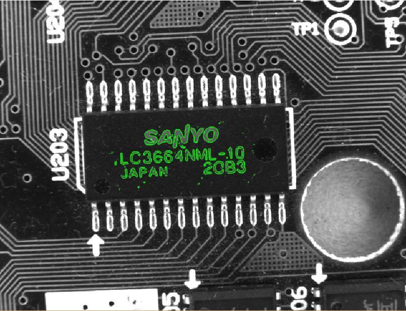
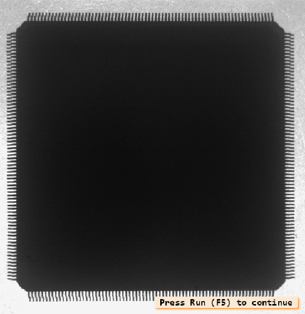
测量IC-measure_pin
本例的任务是检查集成电路的主要尺寸。
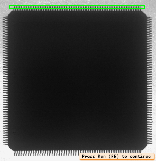
第一步,测量每个引线的范围和引线之间的距离。为此,定义了一个包含引线的矩形用来生成测量对象。这是用来提取垂直于矩形主轴线的直边对。
gen_measure_rectangle2 (Row, Column, Phi, Length1, Length2, Width, Height, 'nearest_neighbor', MeasureHandle)
measure_pairs (Image, MeasureHandle, 1.5, 30, 'negative', 'all', RowEdgeFirst, ColumnEdgeFirst, AmplitudeFirst, RowEdgeSecond, ColumnEdgeSecond, AmplitudeSecond, PinWidth, PinDistance)
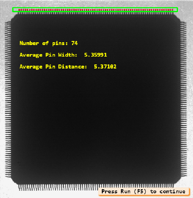
从提取的直边对中,得出引线的数量、平均宽度和它们之间的平均距离。
avgPinWidth := sum(PinWidth) / |PinWidth|
avgPinDistance := sum(PinDistance) / |PinDistance|
numPins := |PinWidth|
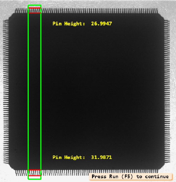
第二部分显示测量工具。尽管每根引线的宽度只有几个像素,导线的长度是可以确定的。为此,一个基于包含IC两边相对引线的矩形的测量对象生成了。第一个和第二个边缘之间的距离是上引线的长度,第三个和第四个边缘之间的距离是下引线的长度。
gen_measure_rectangle2 (Row, Column, Phi, Length1, Length2, Width, Height, 'nearest_neighbor', MeasureHandle)
measure_pos (Image, MeasureHandle, 1.5, 30, 'all', 'all', RowEdge, ColumnEdge, Amplitude, Distance)
源程序
dev_close_window ()
read_image (Image, 'ic_pin')
get_image_size (Image, Width, Height)
dev_open_window (0, 0, Width / 2, Height / 2, 'black', WindowHandle)
set_display_font (WindowHandle, 14, 'mono', 'true', 'false')
dev_display (Image)
disp_continue_message (WindowHandle, 'black', 'true')
stop ()
* draw_rectangle2 (WindowHandle, Row, Column, Phi, Length1, Length2)
Row := 47
Column := 485
Phi := 0
Length1 := 420
Length2 := 10
dev_set_color ('green')
dev_set_draw ('margin')
dev_set_line_width (3)
gen_rectangle2 (Rectangle, Row, Column, Phi, Length1, Length2)
gen_measure_rectangle2 (Row, Column, Phi, Length1, Length2, Width, Height, 'nearest_neighbor', MeasureHandle)
disp_continue_message (WindowHandle, 'black', 'true')
stop ()
dev_update_pc ('off')
dev_update_var ('off')
n := 100
count_seconds (Seconds1)
for i := 1 to n by 1
    measure_pairs (Image, MeasureHandle, 1.5, 30, 'negative', 'all', RowEdgeFirst, ColumnEdgeFirst, AmplitudeFirst, RowEdgeSecond, ColumnEdgeSecond, AmplitudeSecond, PinWidth, PinDistance)
endfor
count_seconds (Seconds2)
Time := Seconds2 - Seconds1
disp_continue_message (WindowHandle, 'black', 'true')
stop ()
dev_set_color ('red')
disp_line (WindowHandle, RowEdgeFirst, ColumnEdgeFirst, RowEdgeSecond, ColumnEdgeSecond)
avgPinWidth := sum(PinWidth) / |PinWidth|
avgPinDistance := sum(PinDistance) / |PinDistance|
numPins := |PinWidth|
dev_set_color ('yellow')
disp_message (WindowHandle, 'Number of pins: ' + numPins, 'image', 200, 100, 'yellow', 'false')
disp_message (WindowHandle, 'Average Pin Width:  ' + avgPinWidth, 'image', 260, 100, 'yellow', 'false')
disp_message (WindowHandle, 'Average Pin Distance:  ' + avgPinDistance, 'image', 320, 100, 'yellow', 'false')
* dump_window (WindowHandle, 'tiff_rgb', 'C:\\Temp\\pins_result')
disp_continue_message (WindowHandle, 'black', 'true')
stop ()
* draw_rectangle1 (WindowHandle, Row1, Column1, Row2, Column2)
Row1 := 0
Column1 := 600
Row2 := 100
Column2 := 700
dev_set_color ('blue')
disp_rectangle1 (WindowHandle, Row1, Column1, Row2, Column2)
stop ()
dev_set_part (Row1, Column1, Row2, Column2)
dev_display (Image)
dev_set_color ('green')
dev_display (Rectangle)
dev_set_color ('red')
disp_line (WindowHandle, RowEdgeFirst, ColumnEdgeFirst, RowEdgeSecond, ColumnEdgeSecond)
disp_continue_message (WindowHandle, 'black', 'true')
stop ()
dev_set_part (0, 0, Height - 1, Width - 1)
dev_display (Image)
disp_continue_message (WindowHandle, 'black', 'true')
stop ()
dev_set_color ('green')
* draw_rectangle2 (WindowHandle, Row, Column, Phi, Length1, Length2)
Row := 508
Column := 200
Phi := -1.5708
Length1 := 482
Length2 := 35
gen_rectangle2 (Rectangle, Row, Column, Phi, Length1, Length2)
gen_measure_rectangle2 (Row, Column, Phi, Length1, Length2, Width, Height, 'nearest_neighbor', MeasureHandle)
stop ()
measure_pos (Image, MeasureHandle, 1.5, 30, 'all', 'all', RowEdge, ColumnEdge, Amplitude, Distance)
PinHeight1 := RowEdge[1] - RowEdge[0]
PinHeight2 := RowEdge[3] - RowEdge[2]
dev_set_color ('red')
disp_line (WindowHandle, RowEdge, ColumnEdge - Length2, RowEdge, ColumnEdge + Length2)
disp_message (WindowHandle, 'Pin Height:  ' + PinHeight1, 'image', RowEdge[1] + 40, ColumnEdge[1] + 100, 'yellow', 'false')
disp_message (WindowHandle, 'Pin Height:  ' + PinHeight2, 'image', RowEdge[3] - 120, ColumnEdge[3] + 100, 'yellow', 'false')
* dump_window (WindowHandle, 'tiff_rgb', 'C:\\Temp\\pins_height_result')
dev_set_draw ('fill')
dev_set_line_width (1)