深入學習OpenCV文檔掃描及OCR識別(文檔掃描,圖像矯正,透視變換,OCR識別)
如果需要處理的原圖及代碼,請移步小編的GitHub地址
傳送門:請點擊我
如果點擊有誤://github.com/LeBron-Jian/ComputerVisionPractice
下面準備學習如何對文檔掃描擺正及其OCR識別的案例,主要想法是對一張不規則的文檔進行矯正,然後通過tesseract進行OCR文字識別,最後返回結果。下面進入正文:
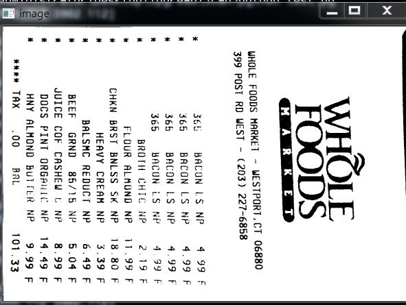
現代生活中,手機像素比較高,所以大家拍這些照片都很隨意,隨便拍,比如下面的照片,如發票,文本等等:
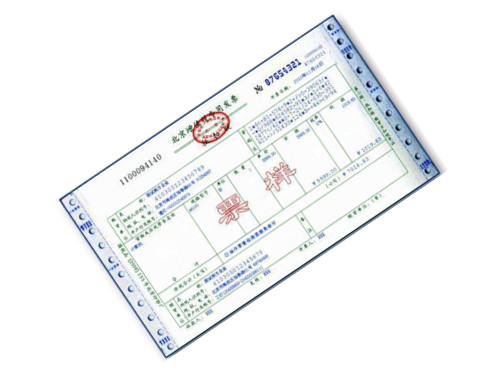
對於這些圖像矯正的問題,在圖像處理領域還真的很多,比如文本的矯正,車牌的矯正,身份證的矯正等等。這些都是因為拍攝者拍照隨意,這就要求我們通過後期的圖像處理技術將圖片還原好,才能進行下一步處理,比如數字分割,數字識別,字母識別,文字識別等等。
上面的問題,我們在日常生活中遇到的可不少,因為拍攝時拍的不好,導致拍出來的圖片歪歪扭扭的,很不自然,那麼我們如何將圖片矯正過來呢?
總的來說,要進行圖像矯正,至少需要以下幾步:
- 1,文檔的輪廓提取技術
- 2,原始與變換坐標的計算
- 3,通過透視變換獲取目標區域
本文通過兩個案例,一個是菜單矯正及OCR識別;另一個是答題卡矯正及OCR識別。
1,如何掃描菜單並獲取菜單內容
下面以菜單為例,慢慢剖析如何實現圖像矯正,並獲取菜單內容。

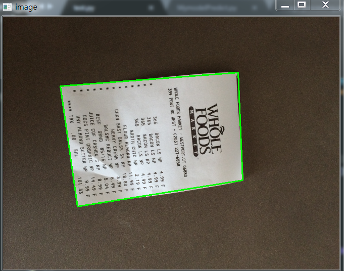
上面的斜着的菜單,如何掃描到如右圖所示的照片呢?其實步驟有以下幾步:
- 1,探測邊緣
- 2,提取菜單矩陣輪廓四點進行透視變換
- 3,應用一個透視的轉換去獲取一個文檔的自頂向下的正圖
知道步驟後,我們開始做吧!
1.1,文檔輪廓提取
我們拿到圖像之後,首先進行邊緣檢測,其中預處理包括對噪音進行高斯模糊,然後進行邊緣檢測(這裡採用了Canny算子提取特徵),下面我們可以看一下邊緣檢測的代碼與結果:
代碼:
def edge_detection(img_path):
    # 讀取輸入
    img = cv2.imread(img_path)
    # 坐標也會相同變換
    ratio = img.shape[0] / 500.0
    orig = img.copy()

    image = resize(orig, height=500)
    # 預處理
    gray = cv2.cvtColor(image, cv2.COLOR_BGR2GRAY)
    blur = cv2.GaussianBlur(gray, (5, 5), 0)
    edged = cv2.Canny(blur, 75, 200)
    show(edged)
效果如下:

我們從上圖可以看到,已經將菜單的所有輪廓都檢測出來了,而我們其實只需要最外面的輪廓,下面我們通過過濾得到最邊緣的輪廓即可。
代碼如下:
def edge_detection(img_path):
    # *********  預處理 ****************
    # 讀取輸入
    img = cv2.imread(img_path)
    # 坐標也會相同變換
    ratio = img.shape[0] / 500.0
    orig = img.copy()

    image = resize(orig, height=500)
    # 預處理
    gray = cv2.cvtColor(image, cv2.COLOR_BGR2GRAY)
    blur = cv2.GaussianBlur(gray, (5, 5), 0)
    edged = cv2.Canny(blur, 75, 200)

    # *************  輪廓檢測 ****************
    # 輪廓檢測
    contours, hierarchy = cv2.findContours(edged.copy(), cv2.RETR_LIST, cv2.CHAIN_APPROX_SIMPLE)
    cnts = sorted(contours, key=cv2.contourArea, reverse=True)[:5]

    # 遍歷輪廓
    for c in cnts:
        # 計算輪廓近似
        peri = cv2.arcLength(c, True)
        # c表示輸入的點集,epsilon表示從原始輪廓到近似輪廓的最大距離,它是一個準確度參數
        approx = cv2.approxPolyDP(c, 0.02*peri, True)

        # 4個點的時候就拿出來
        if len(approx) == 4:
            screenCnt = approx
            break

    res = cv2.drawContours(image, [screenCnt], -1, (0, 255, 0), 2)
    show(res)
效果如下:
如果說對輪廓排序後,不進行近似的話,我們直接取最大的輪廓,效果圖如下:

1.2,透視變換(擺正圖像)
當獲取到圖片的最外輪廓後,接下來,我們需要擺正圖像,在擺正圖形之前,我們需要先學習透視變換。
1.2.1,cv2.getPerspectiveTransform()
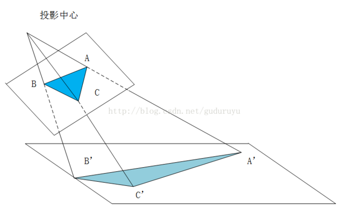
透視變換(Perspective Transformation)是將成像投影到一個新的視平面(Viewing Plane),也稱作投影映射(Projective mapping),如下圖所示,通過透視變換ABC變換到A’B’C’。
cv2.getPerspectiveTransform() 獲取投射變換後的H矩陣。
cv2.getPerspectiveTransform() 函數的opencv 源碼如下:
def getPerspectiveTransform(src, dst, solveMethod=None): # real signature unknown; restored from __doc__
    """
    getPerspectiveTransform(src, dst[, solveMethod]) -> retval
    .   @brief Calculates a perspective transform from four pairs of the corresponding points.
    .
    .   The function calculates the \f$3 \times 3\f$ matrix of a perspective transform so that:
    .
    .   \f[\begin{bmatrix} t_i x'_i \\ t_i y'_i \\ t_i \end{bmatrix} = \texttt{map_matrix} \cdot \begin{bmatrix} x_i \\ y_i \\ 1 \end{bmatrix}\f]
    .
    .   where
    .
    .   \f[dst(i)=(x'_i,y'_i), src(i)=(x_i, y_i), i=0,1,2,3\f]
    .
    .   @param src Coordinates of quadrangle vertices in the source image.
    .   @param dst Coordinates of the corresponding quadrangle vertices in the destination image.
    .   @param solveMethod method passed to cv::solve (#DecompTypes)
    .
    .   @sa  findHomography, warpPerspective, perspectiveTransform
    """
    pass
參數說明:
- rect(即函數中src)表示待測矩陣的左上,右上,右下,左下四點坐標
- transform_axes(即函數中dst)表示變換後四個角的坐標,即目標圖像中矩陣的坐標
返回值由原圖像中矩陣到目標圖像矩陣變換的矩陣,得到矩陣接下來則通過矩陣來獲得變換後的圖像,下面我們學習第二個函數。
1.2.2,cv2.warpPerspective()
cv2.warpPerspective() 根據H獲得變換後的圖像。
opencv源碼如下:
def warpPerspective(src, M, dsize, dst=None, flags=None, borderMode=None, borderValue=None): # real signature unknown; restored from __doc__
    """
    warpPerspective(src, M, dsize[, dst[, flags[, borderMode[, borderValue]]]]) -> dst
    .   @brief Applies a perspective transformation to an image.
    .
    .   The function warpPerspective transforms the source image using the specified matrix:
    .
    .   \f[\texttt{dst} (x,y) =  \texttt{src} \left ( \frac{M_{11} x + M_{12} y + M_{13}}{M_{31} x + M_{32} y + M_{33}} ,
    .        \frac{M_{21} x + M_{22} y + M_{23}}{M_{31} x + M_{32} y + M_{33}} \right )\f]
    .
    .   when the flag #WARP_INVERSE_MAP is set. Otherwise, the transformation is first inverted with invert
    .   and then put in the formula above instead of M. The function cannot operate in-place.
    .
    .   @param src input image.
    .   @param dst output image that has the size dsize and the same type as src .
    .   @param M \f$3\times 3\f$ transformation matrix.
    .   @param dsize size of the output image.
    .   @param flags combination of interpolation methods (#INTER_LINEAR or #INTER_NEAREST) and the
    .   optional flag #WARP_INVERSE_MAP, that sets M as the inverse transformation (
    .   \f$\texttt{dst}\rightarrow\texttt{src}\f$ ).
    .   @param borderMode pixel extrapolation method (#BORDER_CONSTANT or #BORDER_REPLICATE).
    .   @param borderValue value used in case of a constant border; by default, it equals 0.
    .
    .   @sa  warpAffine, resize, remap, getRectSubPix, perspectiveTransform
    """
    pass
參數說明:
- src 表示輸入的灰度圖像
- M 表示變換矩陣
- dsize 表示目標圖像的shape,(width, height)表示變換後的圖像大小
- flags:插值方式,interpolation方法INTER_LINEAR或者INTER_NEAREST
- borderMode:邊界補償方式,BORDER_CONSTANT or BORDER_REPLCATE
- borderValue:邊界補償大小,常值,默認為0
1.2.3 cv2.perspectiveTransform()
cv2.perspectiveTransform() 和 cv2.warpPerspective()大致作用相同,但是區別在於 cv2.warpPerspective()適用於圖像,而cv2.perspectiveTransform() 適用於一組點。
cv2.perspectiveTransform() 的opencv源碼如下:
def perspectiveTransform(src, m, dst=None): # real signature unknown; restored from __doc__
    """
    perspectiveTransform(src, m[, dst]) -> dst
    .   @brief Performs the perspective matrix transformation of vectors.
    .
    .   The function cv::perspectiveTransform transforms every element of src by
    .   treating it as a 2D or 3D vector, in the following way:
    .   \f[(x, y, z)  \rightarrow (x'/w, y'/w, z'/w)\f]
    .   where
    .   \f[(x', y', z', w') =  \texttt{mat} \cdot \begin{bmatrix} x & y & z & 1  \end{bmatrix}\f]
    .   and
    .   \f[w =  \fork{w'}{if \(w' \ne 0\)}{\infty}{otherwise}\f]
    .
    .   Here a 3D vector transformation is shown. In case of a 2D vector
    .   transformation, the z component is omitted.
    .
    .   @note The function transforms a sparse set of 2D or 3D vectors. If you
    .   want to transform an image using perspective transformation, use
    .   warpPerspective . If you have an inverse problem, that is, you want to
    .   compute the most probable perspective transformation out of several
    .   pairs of corresponding points, you can use getPerspectiveTransform or
    .   findHomography .
    .   @param src input two-channel or three-channel floating-point array; each
    .   element is a 2D/3D vector to be transformed.
    .   @param dst output array of the same size and type as src.
    .   @param m 3x3 or 4x4 floating-point transformation matrix.
    .   @sa  transform, warpPerspective, getPerspectiveTransform, findHomography
    """
    pass
參數含義:
- src:輸入的二通道或三通道的圖像
- m:變換矩陣
- 返回結果為相同size的圖像
1.2.4 擺正圖像
將圖像框出來後,我們計算出變換前後的四個點的坐標,然後得到最終的變換結果。
代碼如下:
def order_points(pts):
    # 一共四個坐標點
    rect = np.zeros((4, 2), dtype='float32')

    # 按順序找到對應的坐標0123 分別是左上,右上,右下,左下
    # 計算左上,由下
    # numpy.argmax(array, axis) 用於返回一個numpy數組中最大值的索引值
    s = pts.sum(axis=1)  # [2815.2   1224.    2555.712 3902.112]
    print(s)
    rect[0] = pts[np.argmin(s)]
    rect[2] = pts[np.argmax(s)]

    # 計算右上和左
    # np.diff()  沿着指定軸計算第N維的離散差值  後者-前者
    diff = np.diff(pts, axis=1)
    rect[1] = pts[np.argmin(diff)]
    rect[3] = pts[np.argmax(diff)]
    return rect


# 透視變換
def four_point_transform(image, pts):
    # 獲取輸入坐標點
    rect = order_points(pts)
    (tl, tr, br, bl) = rect

    # 計算輸入的w和h的值
    widthA = np.sqrt(((br[0] - bl[0])**2) + ((br[1] - bl[1])**2))
    widthB = np.sqrt(((tr[0] - tl[0])**2) + ((tr[1] - tl[1])**2))
    maxWidth = max(int(widthA), int(widthB))

    heightA = np.sqrt(((tr[0] - br[0])**2) + ((tr[1] - br[1])**2))
    heightB = np.sqrt(((tl[0] - bl[0])**2) + ((tl[1] - bl[1])**2))
    maxHeight = max(int(heightA), int(heightB))

    # 變化後對應坐標位置
    dst = np.array([
        [0, 0],
        [maxWidth - 1, 0],
        [maxWidth - 1, maxHeight - 1],
        [0, maxHeight - 1]],
        dtype='float32')

    # 計算變換矩陣
    M = cv2.getPerspectiveTransform(rect, dst)
    warped = cv2.warpPerspective(image, M, (maxWidth, maxHeight))

    # 返回變換後的結果
    return warped


# 對透視變換結果進行處理
def get_image_processingResult():
    img_path = 'images/receipt.jpg'
    orig, ratio, screenCnt = edge_detection(img_path)
    # screenCnt 為四個頂點的坐標值,但是我們這裡需要將圖像還原,即乘以以前的比率
    # 透視變換  這裡我們需要將變換後的點還原到原始坐標裏面
    warped = four_point_transform(orig, screenCnt.reshape(4, 2)*ratio)
    # 二值處理
    gray = cv2.cvtColor(warped, cv2.COLOR_BGR2GRAY)
    thresh = cv2.threshold(gray, 100, 255, cv2.THRESH_BINARY)[1]

    thresh_resize = resize(thresh, height = 400)
    show(thresh_resize)
效果如下:
1.2.5 其他圖片矯正實踐
這裡圖片原圖都可以去我的GitHub裏面去拿(地址://github.com/LeBron-Jian/ComputerVisionPractice)。
對於下面這張圖:
我們使用透視變換摳出來效果如下:
這個圖使用和之前的代碼就可以,不用修改任何東西就可以拿到其目標區域。
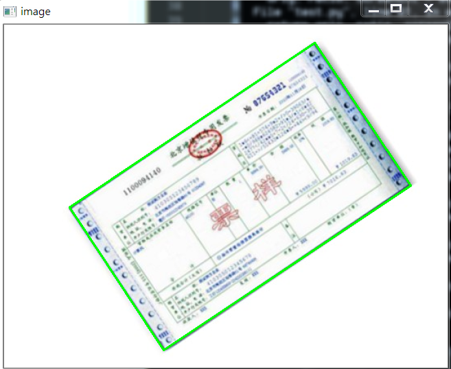
下面看這張圖:
其實和上面圖類似,不過這裡我們依次看一下其圖像處理過程,畢竟和上面兩張圖完全不是一個類型了。
首先是 Canny算子得到的結果:

其實拿到全輪廓後,我們就直接獲取最外面的輪廓即可。
我自己更改了一下,效果一樣,但是還是貼上代碼:
def edge_detection(img_path):
    # *********  預處理 ****************
    # 讀取輸入
    img = cv2.imread(img_path)
    # 坐標也會相同變換
    ratio = img.shape[0] / 500.0
    orig = img.copy()

    image = resize(orig, height=500)
    # 預處理
    gray = cv2.cvtColor(image, cv2.COLOR_BGR2GRAY)
    blur = cv2.GaussianBlur(gray, (5, 5), 0)
    edged = cv2.Canny(blur, 75, 200)
    # show(edged)
    # *************  輪廓檢測 ****************
    # 輪廓檢測
    contours, hierarchy = cv2.findContours(edged.copy(), cv2.RETR_LIST, cv2.CHAIN_APPROX_SIMPLE)
    #cnts = sorted(contours, key=cv2.contourArea, reverse=True)[:5]

    max_area = 0
    myscreenCnt = []
    for i in contours:
        temp = cv2.contourArea(i)
        if max_area < temp:
            myscreenCnt = i

    # res = cv2.drawContours(image, myscreenCnt, -1, (0, 255, 0), 2)
    # show(res)
    return orig, ratio, screenCnt
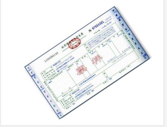
最後我們不對發票做任何處理,看原圖效果:
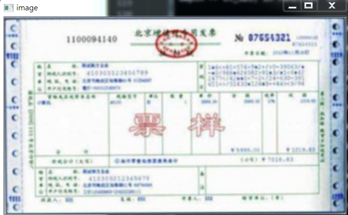
部分代碼如下:
# 對透視變換結果進行處理
def get_image_processingResult():
    img_path = 'images/fapiao.jpg'
    orig, ratio, screenCnt = edge_detection(img_path)
    # screenCnt 為四個頂點的坐標值,但是我們這裡需要將圖像還原,即乘以以前的比率
    # 透視變換  這裡我們需要將變換後的點還原到原始坐標裏面
    warped = four_point_transform(orig, screenCnt.reshape(4, 2)*ratio)

    thresh_resize = resize(warped, height = 400)
    show(thresh_resize)
    return thresh
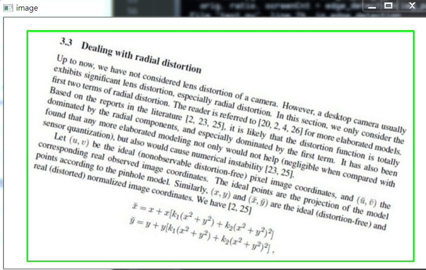
下面再看一個例子:

首先,它得到的Canny結果如下:

我們需要對它進行一些小小的處理。
我做了一些嘗試,如果直接對膨脹後的圖像,進行外接矩形,那麼效果如下:
代碼如下:
    x, y, w, h = cv2.boundingRect(myscreenCnt)
    res = cv2.rectangle(image, (x,y), (x+w,y+h), (0, 255, 0), 2)
    show(res)
所以對輪廓取近似,效果稍微好點:
    # 計算輪廓近似
    peri = cv2.arcLength(myscreenCnt, True)
    # c表示輸入的點集,epsilon表示從原始輪廓到近似輪廓的最大距離,它是一個準確度參數
    approx = cv2.approxPolyDP(myscreenCnt, 0.015*peri, True)
    res = cv2.drawContours(image, [approx], -1, (0, 255, 0), 2)
    show(res)
效果如下:
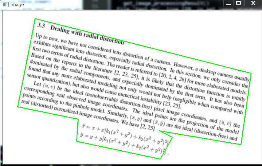
因為這個是不規整圖形,所以無法進行四個角的轉換,需要更多角,這裡不再繼續嘗試。
1.3,OCR識別
這裡回到我們的菜單來,我們已經得到了掃描後的結果,下面我們進行OCR文字識別。
這裡使用tesseract進行識別,不懂的可以參考我之前的博客(包括安裝tesseract,和通過tesseract訓練自己的字庫):
深入學習使用ocr算法識別圖片中文字的方法
深入學習Tesseract-ocr識別中文並訓練字庫的方法
配置好tesseract之後(這裡不再show過程,因為我已經有了),我們通過其進行文字識別。
1.3.1 通過Python使用tesseract的坑
如果直接使用Python進行OCR識別的話,會出現下面問題:
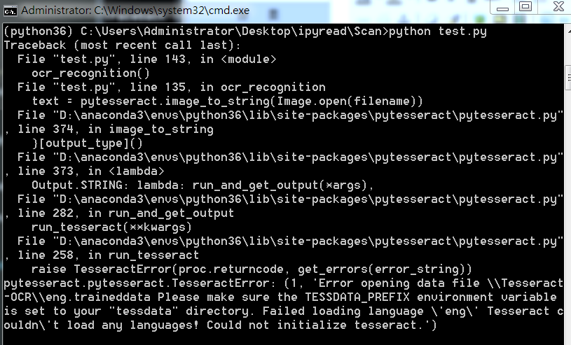
這裡因為anaconda下載的 pytesseract 默認運行的tesseract.exe 是默認文件夾,所以有問題,我們改一下。
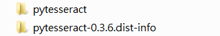
注意,找到安裝地址,我們會發現有兩個文件夾,我們進入上面文件夾即可
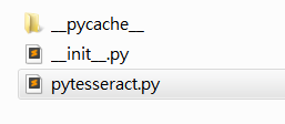
進入之後如下,我們打開 pytesseract.py。
注意這裡的地址:
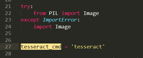
我們需要修改為我們安裝的地址,即使我們之前設置了全局變量,但是Python還是不care的。
這裡注意地址的話,我們通過 / 即可,不要 \,避免windows出現問題。
1.3.2 OCR識別
安裝好一切之後,就可以識別了,我們這裡有兩種方法,一種是直接在人家的環境下運行,一種是在Python中通過安裝pytesseract 庫運行,效果都一樣。
代碼如下:
from PIL import Image
import pytesseract
import cv2
import os

preprocess = 'blur' #thresh

image = cv2.imread('scan.jpg')
gray = cv2.cvtColor(image, cv2.COLOR_BGR2GRAY)

if preprocess == "thresh":
    gray = cv2.threshold(gray, 0, 255,cv2.THRESH_BINARY | cv2.THRESH_OTSU)[1]

if preprocess == "blur":
    gray = cv2.medianBlur(gray, 3)

filename = "{}.png".format(os.getpid())
cv2.imwrite(filename, gray)

text = pytesseract.image_to_string(Image.open(filename))
print(text)
os.remove(filename)

cv2.imshow("Image", image)
cv2.imshow("Output", gray)
cv2.waitKey(0)
使用Python運行,效果如下:
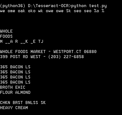
直接在tesseract.exe運行:

效果如下:

可能識別效果不是很好。不過不重要,因為圖片也比較模糊,不是那麼工整的。
1.4,完整代碼
當然也可以去我的GitHub直接去下載。
代碼如下:
import cv2
import numpy as np
from PIL import Image
import pytesseract


def show(image):
    cv2.imshow('image', image)
    cv2.waitKey(0)
    cv2.destroyAllWindows()

def resize(image, width=None, height=None, inter=cv2.INTER_AREA):
    dim = None
    (h, w) = image.shape[:2]
    if width is None and height is None:
        return image
    if width is None:
        r = height / float(h)
        dim = (int(w*r), height)
    else:
        r = width / float(w)
        dim = (width, int(h*r))
    resized = cv2.resize(image, dim, interpolation=inter)
    return resized


def edge_detection(img_path):
    # *********  預處理 ****************
    # 讀取輸入
    img = cv2.imread(img_path)
    # 坐標也會相同變換
    ratio = img.shape[0] / 500.0
    orig = img.copy()

    image = resize(orig, height=500)
    # 預處理
    gray = cv2.cvtColor(image, cv2.COLOR_BGR2GRAY)
    blur = cv2.GaussianBlur(gray, (5, 5), 0)
    edged = cv2.Canny(blur, 75, 200)

    # *************  輪廓檢測 ****************
    # 輪廓檢測
    contours, hierarchy = cv2.findContours(edged.copy(), cv2.RETR_LIST, cv2.CHAIN_APPROX_SIMPLE)
    cnts = sorted(contours, key=cv2.contourArea, reverse=True)[:5]

    # 遍歷輪廓
    for c in cnts:
        # 計算輪廓近似
        peri = cv2.arcLength(c, True)
        # c表示輸入的點集,epsilon表示從原始輪廓到近似輪廓的最大距離,它是一個準確度參數
        approx = cv2.approxPolyDP(c, 0.02*peri, True)

        # 4個點的時候就拿出來
        if len(approx) == 4:
            screenCnt = approx
            break

    # res = cv2.drawContours(image, [screenCnt], -1, (0, 255, 0), 2)
    # res = cv2.drawContours(image, cnts[0], -1, (0, 255, 0), 2)
    # show(orig)
    return orig, ratio, screenCnt


def order_points(pts):
    # 一共四個坐標點
    rect = np.zeros((4, 2), dtype='float32')

    # 按順序找到對應的坐標0123 分別是左上,右上,右下,左下
    # 計算左上,由下
    # numpy.argmax(array, axis) 用於返回一個numpy數組中最大值的索引值
    s = pts.sum(axis=1)  # [2815.2   1224.    2555.712 3902.112]
    print(s)
    rect[0] = pts[np.argmin(s)]
    rect[2] = pts[np.argmax(s)]

    # 計算右上和左
    # np.diff()  沿着指定軸計算第N維的離散差值  後者-前者
    diff = np.diff(pts, axis=1)
    rect[1] = pts[np.argmin(diff)]
    rect[3] = pts[np.argmax(diff)]
    return rect


# 透視變換
def four_point_transform(image, pts):
    # 獲取輸入坐標點
    rect = order_points(pts)
    (tl, tr, br, bl) = rect

    # 計算輸入的w和h的值
    widthA = np.sqrt(((br[0] - bl[0])**2) + ((br[1] - bl[1])**2))
    widthB = np.sqrt(((tr[0] - tl[0])**2) + ((tr[1] - tl[1])**2))
    maxWidth = max(int(widthA), int(widthB))

    heightA = np.sqrt(((tr[0] - br[0])**2) + ((tr[1] - br[1])**2))
    heightB = np.sqrt(((tl[0] - bl[0])**2) + ((tl[1] - bl[1])**2))
    maxHeight = max(int(heightA), int(heightB))

    # 變化後對應坐標位置
    dst = np.array([
        [0, 0],
        [maxWidth - 1, 0],
        [maxWidth - 1, maxHeight - 1],
        [0, maxHeight - 1]],
        dtype='float32')

    # 計算變換矩陣
    M = cv2.getPerspectiveTransform(rect, dst)
    warped = cv2.warpPerspective(image, M, (maxWidth, maxHeight))

    # 返回變換後的結果
    return warped


# 對透視變換結果進行處理
def get_image_processingResult():
    img_path = 'images/receipt.jpg'
    orig, ratio, screenCnt = edge_detection(img_path)
    # screenCnt 為四個頂點的坐標值,但是我們這裡需要將圖像還原,即乘以以前的比率
    # 透視變換  這裡我們需要將變換後的點還原到原始坐標裏面
    warped = four_point_transform(orig, screenCnt.reshape(4, 2)*ratio)
    # 二值處理
    gray = cv2.cvtColor(warped, cv2.COLOR_BGR2GRAY)
    thresh = cv2.threshold(gray, 100, 255, cv2.THRESH_BINARY)[1]

    cv2.imwrite('scan.jpg', thresh)

    thresh_resize = resize(thresh, height = 400)
    # show(thresh_resize)
    return thresh


def ocr_recognition(filename='tes.jpg'):
    img = Image.open(filename)
    text = pytesseract.image_to_string(img)
    print(text)


if __name__ == '__main__':
    # 獲取矯正之後的圖片
    # get_image_processingResult()
    # 進行OCR文字識別
    ocr_recognition()
2,如何掃描答題卡並識別
答題卡識別判卷,大家應該都不陌生。那麼它需要做什麼呢?肯定是將我們在答題卡上畫圈圈的地方識別出來。
這是答題卡樣子(原圖請去我GitHub上拿://github.com/LeBron-Jian/ComputerVisionPractice):
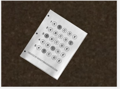
我們肯定是需要分為兩步走,第一步就是和上面處理類似,拿到答題卡的最終透視變換結果,使得圖片中的答題卡可以凸顯出來。第二步就是根據正確答案和答題卡的答案來判斷正確率。
2.1 掃描答題卡及透視變換
這裡我們對答題卡進行透視變換,因為之前已經詳細的學習了這一部分,這裡不再贅述,只是簡單記錄一下流程和圖像處理效果,並展示代碼。
下面詳細的總結處理步驟:
- 1,圖像灰度化
- 2,高斯濾波處理
- 3,使用Canny算子找到圖片邊緣信息
- 4,尋找輪廓
- 5,找到最外層輪廓,並確定四個坐標點
- 6,根據四個坐標位置計算出變換後的四個角位置
- 7,獲取變換矩陣H,得到最終變換結果
下面直接使用上面代碼進行跑,首先展示Canny效果:
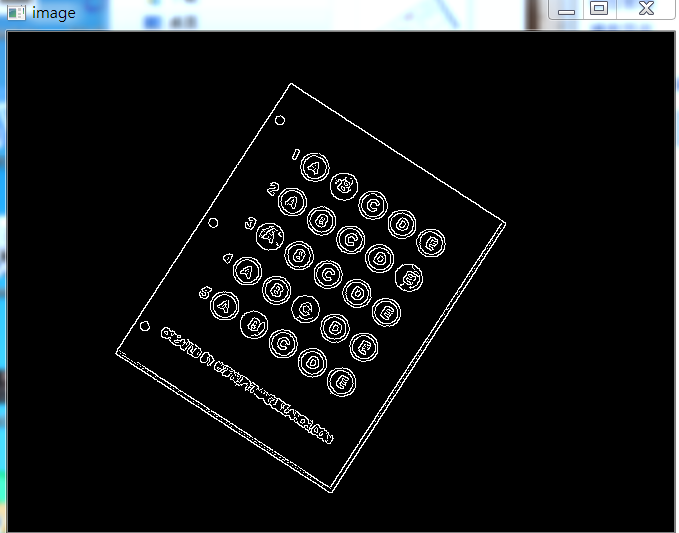
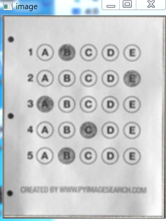
當Canny效果不錯的時候,我們拿到圖像的輪廓進行篩選,找到最外面的輪廓,如下圖所示:

最後通過透視變換,獲得答題卡的區域,如下圖所示:
2.2 根據正確答案和圖卡判斷正確率
這裡我們拿到上面得到的答題卡圖像,然後進行操作,獲取到塗的位置,然後和正確答案比較,最後獲得正確率。
這裡分為以下幾個步驟:
- 1,對圖像進行二值化,將塗了顏色的地方變為白色
- 2,對輪廓進行篩選,找到正確答案的輪廓
- 3,對輪廓從上到下進行排序
- 4,計算顏色最大值的位置和Nonezeros的值
- 5,結合正確答案計算正確率
- 6,將正確答案打印在圖像上
下面開始實踐:
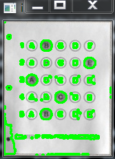
首先對圖像進行二值化,如下圖所示:

如果對二值化後的圖直接進行畫輪廓,如下:
所以不能直接處理,這裡我們需要做細微處理,然後拿到圖像如下:

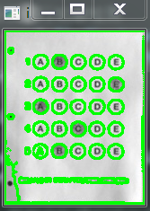
這樣就可以獲得其塗的輪廓,如下所示:
然後篩選出我們需要的塗了答題卡的位置,效果如下:

然後通過這五個坐標點,確定答題卡的位置,如下圖所示:

然後根據真實答案和圖中答案對比結果,我們將最終結果與圈出來答案展示在圖上,如下:

此項目到此結束。
2.3 部分代碼展示
完整代碼可以去我的GitHub上拿(地址://github.com/LeBron-Jian/ComputerVisionPractice)
代碼如下:
import cv2
import numpy as np
from PIL import Image
import pytesseract


def show(image):
    cv2.imshow('image', image)
    cv2.waitKey(0)
    cv2.destroyAllWindows()


def sorted_contours(cnt, model='left-to-right'):
    if model == 'top-to-bottom':
        cnt = sorted(cnt, key=lambda x:cv2.boundingRect(x)[1])

    elif model == 'left-to-right':
        cnt = sorted(cnt, key=lambda x:cv2.boundingRect(x)[0])

    return cnt

# 正確答案
ANSWER_KEY = {0:1, 1:4, 2:0, 3:3, 4:1}

def answersheet_comparison(filename='finalanswersheet.jpg'):
    '''
        對變換後的圖像進行操作(wraped),構造mask
        根據有無填塗的特性,進行位置的計算
    '''
    img = cv2.imread(filename)
    # print(img.shape)   # 156*194
    gray = cv2.cvtColor(img, cv2.COLOR_BGR2GRAY)
    # 對圖像進行二值化操作
    thresh = cv2.threshold(gray, 0, 255, cv2.THRESH_BINARY_INV | cv2.THRESH_OTSU)[1]
    # show(thresh)

    # 對圖像進行細微處理
    kernele = cv2.getStructuringElement(cv2.MORPH_ELLIPSE, ksize=(3, 3))
    erode = cv2.erode(thresh, kernele)
    kerneld = cv2.getStructuringElement(cv2.MORPH_ELLIPSE, ksize=(3, 3))
    dilate = cv2.dilate(erode, kerneld)
    # show(dilate)

    # 對圖像進行輪廓檢測
    cnts = cv2.findContours(dilate, cv2.RETR_EXTERNAL, cv2.CHAIN_APPROX_SIMPLE)[0]
    # res = cv2.drawContours(img.copy(), cnts, -1, (0, 255, 0), 2)
    # # show(res)


    questionCnts = []
    for c in cnts:
        (x, y, w, h) = cv2.boundingRect(c)
        arc = w/float(h)

        # 根據實際情況找出合適的輪廓
        if  w > 8 and h > 8 and arc >= 0.7 and arc <= 1.3:
            questionCnts.append(c)

    # print(len(questionCnts))  # 這裡總共圈出五個輪廓 分別為五個位置的輪廓
    # 第四步,將輪廓進行從上到下的排序
    questionCnts = sorted_contours(questionCnts, model='top-to-bottom')


    correct = 0
    all_length = len(questionCnts)
    for i in range(len(questionCnts)):
        x, y, w, h = cv2.boundingRect(questionCnts[i])
        answer = round((x-32)/float(100)*5)
        print(ANSWER_KEY[i])
        if answer == ANSWER_KEY[i]:
            correct += 1
            img = cv2.drawContours(img, questionCnts[i], -1, 0, 2)

    score = float(correct)/float(all_length)
    print(correct, all_length, score)

    cv2.putText(img, 'correct_score:%s'%score, (10, 15), cv2.FONT_HERSHEY_SIMPLEX,
        0.4, 0.3)
    show(img)


if __name__ == '__main__':
    answersheet_comparison()
參考文獻://www.pyimagesearch.com/2014/09/01/build-kick-ass-mobile-document-scanner-just-5-minutes/
//blog.csdn.net/weixin_30666753/article/details/99054383
//www.cnblogs.com/my-love-is-python/archive/2004/01/13/10439224.html