【芯片手册开发】Sil9136音频开发详细分析+源码实战
- 2020 年 11 月 20 日
- 筆記
- /label/lzm, /label/manual, 芯片手册
前言
- 默认在开发了视频方面后
- 这方面的工作本来可以找技术支持拿个例程参考下,很快就可以的写出来的,以为自己对HDMI协议不太了解,但是技术支持说没有,所以没办法,只能自己搞了
- 看手册不难,难得找是资料
- 记录一下,也分享一下
参考
- sil9136寄存器手册:《Sil-PR-1060-C》
- HDMI协议手册:《HDMI_1.4》
- CEA标准手册:《CEA-861-D[安全]》
- 使用参考例程(无音频功能)
手册使用+实战
- 以 I2S 接口为例开发
- 直接看手册配置相关寄存器
- 记得输入与输出配对
- 如编码类型
- 采样长度
- 采样频率
- 等等
配置
-
《Sil-PR-1060-C》手册,28页起
-
图中说明 sil9136 支持 S/PDIF, I2S or DSD模式,主机可以通过配置TPI选择不同的模式
-
这个寄存器表比较重要,说明了sil9136的寄存器配置
-
0x26 寄存器
- [7:6]
- 选择模式,支持
- none
- S/PDIF
- I2S
- DSD
- 选择模式,支持
- [5]
- 通道数,支持
- 双通道
- 8 通道
- 通道数,支持
- [4]
- 静音配置
- [3:0]
- 编码类型,有
- Refer to Stream Header
- PCM (本次使用 PCM)
- AC-3
- MPEG1
- MP3
- MPEG2
- AAC
- DTS
- ATRAC
- 编码类型,有
- [7:6]
-
0x27 寄存器
- [7:6]
- 音频采样比特位长度 SS
- Refer to Stream Header
- 16 bit
- 20 bit
- 24 bit
- 音频采样比特位长度 SS
- [5:3]
- 音频采样频率 SF
- Refer to Stream Header
- 32 kHz
- 44.1 kHz
- 48 kHz
- 88.2 kHz
- 96 kHz
- 176.4 kHz
- 192 kHz
- 音频采样频率 SF
- [2]
- 是否支持高比特率
- [7:6]
-
注意:图中说明的 0x24 和 0x25 寄存器只有在 S/PDIF 模式下有效,即是 0x26[7:6]=01 时。
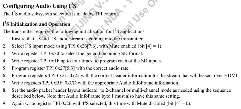
Configuring Audio Using I2S
-
直接跳到配置 I2S 流程,实现配置逻辑
-

- 上图已经很明显地显示出了配置出 I2S 的流程了
- 步骤:
- 确保有有效的 I2S 信号进入 sil9136
- 设置 0x26[4] 为静音模式
- 直接调用例程接口:
SetAudioMute(AUDIO_MUTE_MUTED);
- 直接调用例程接口:
- 通过 0x20 来配置进来的 SD 格式
-

- 配置要和输入的音频配置搭配
- 以下为个人选择
- SCK Sample Edge :Rising
- MCLK Multiplier:256
- WS Polarity – Left when:WS is Low
- SD Justify Data is justified:Left
- SD Direction Byte shifted first:MSB
- WS to SD First Bit Shift:Yes
- 程序为:
WriteByteTPI(TPI_I2S_IN_CFG, (0x80x10));
-
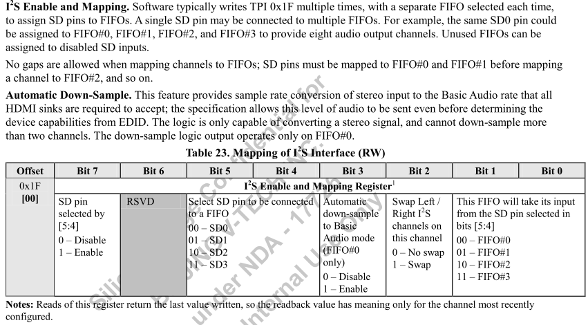
- 通过多次设置 0x1F 来配置每一个 SD 输入映射
-

- SDx与FIFOn的映射
- 支持一对多
- 注意:必须顺序映射,如如果要映射FIFO2,就必须先完成FIFO0和FIFO1的映射
- 我的代码段:SD0-FIFO0; SD1-FIFO1; SD2-FIFO2; SD3-FIFO3;
do{
        WriteByteTPI(TPI_I2S_EN, 0x80);
        Tmp = ReadByteTPI(TPI_I2S_EN);
    }while(Tmp != 0x80);
    do{
        WriteByteTPI(TPI_I2S_EN, 0x91);
        Tmp = ReadByteTPI(TPI_I2S_EN);
    }while(Tmp != 0x91);
    do{
        WriteByteTPI(TPI_I2S_EN, 0xA2);
        Tmp = ReadByteTPI(TPI_I2S_EN);
    }while(Tmp != 0xA2);
    do{
        WriteByteTPI(TPI_I2S_EN, 0xB3);
        Tmp = ReadByteTPI(TPI_I2S_EN);
    }while(Tmp != 0xB3);
-
- 通过设置 0x27[5:3] 来配置音频采样频率
- 配置为48kHz:
ReadModifyWriteTPI(TPI_AUDIO_SAMPLE_CTRL, 0x38, 0x18);
- 配置为48kHz:
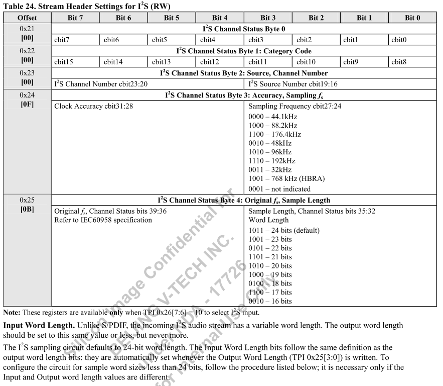
- 设置 0x21-0x25 来配置发送到HDMI的头信息
-

- 上图 0x21-0x25 的描述在 I2S 模式有效,即是 0x26[7:6] = 0x10
- 主要配置两个参数
- 采样频率:48 kHz
- 采样长度:24 bits
- 代码段
    WriteByteTPI(TPI_I2S_CHST_0, 0x00);
    WriteByteTPI(TPI_I2S_CHST_1, 0x00);
    WriteByteTPI(TPI_I2S_CHST_2, 0x00);
    WriteByteTPI(TPI_I2S_CHST_3, 0x02);
    WriteByteTPI(TPI_I2S_CHST_4, 0x0B);
-
- 设置 0xBF-0xCD 来配置 audio infoframe
-
这步骤先给出最终代码再分析:
SetAudioInfoFrames(TWO_CHANNELS, 0x00, 0x00, 0x18, 0x00); -

-
说明了配置 audio infoframe 的必要性和需要参考的文件 HDMI Specification,根据本文件说明,了解到sil9136 支持 HDMI1.4 协议,所以准备好文件《HDMI_1.4》,并找到关于 audio infoframe 的说明。
-
图A
-
图B
-
图C
-

-
图Cc1,《CEA-861-D安全》
-
图Cc2,《CEA-861-D安全》
-
-
图D
-
结合例程源码
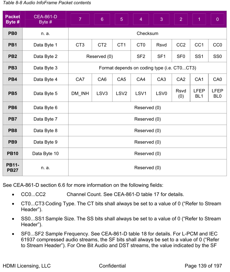
bool SetAudioInfoFrames函数,得出只需要了解几个参数配置即可。- byte ChannelCount
- 参照图C和图Cc1,C0…C2,选择双通道,得出值为 0x01
- byte CodingType
- CT0…CT3: The CT bits shall always be set to a value of 0 (“Refer to Stream Header”).即是置为0即可
- SS
- The SS bits shall always be set to a value of 0 (“Refer to Stream Header”). 即是置为0即可
- Fs
- 参考源码、0x27寄存器、图C和图Cc2
- 推测
Fs就是采样频率 SF0…SF2 B_Data[6] = (Fs >> 1) | (SS >> 6);- Fs在图C中的PB2[4:2],而上述代码中右移一位,所以 Fs 的值占用[5:3],参考0x27。
- 采样频率为 48kHz,得出 Fs=x018
- SpeakerConfig
- 参考源码
B_Data[8] = SpeakerConfig;得出 SpeakerConfig 为 图C中的PB4 - 这里为 LPCM ,所以 SpeakerConfig = 0;
- 参考源码
////////////////////////////////////////////////////////////////////////////// // // FUNCTION : SetAudioInfoFrames() // // PURPOSE : Load Audio InfoFrame data into registers and send to sink // // INPUT PARAMS : (1) Channel count (2) speaker configuration per CEA-861D // Tables 19, 20 (3) Coding type: 0x09 for DSD Audio. 0 (refer // to stream header) for all the rest (4) Sample Frequency. Non // zero for HBR only (5) Audio Sample Length. Non zero for HBR // only. // // OUTPUT PARAMS : None // // GLOBALS USED : None // // RETURNS : TRUE // ////////////////////////////////////////////////////////////////////////////// bool SetAudioInfoFrames(byte ChannelCount, byte CodingType, byte SS, byte Fs, byte SpeakerConfig) { byte B_Data[SIZE_AUDIO_INFOFRAME]; // 14 byte i; TPI_TRACE_PRINT((">>SetAudioInfoFrames()\n")); for (i = 0; i < SIZE_AUDIO_INFOFRAME +1; i++) B_Data[i] = 0; B_Data[0] = EN_AUDIO_INFOFRAMES; // 0xC2 B_Data[1] = TYPE_AUDIO_INFOFRAMES; // 0x84 B_Data[2] = AUDIO_INFOFRAMES_VERSION; // 0x01 B_Data[3] = AUDIO_INFOFRAMES_LENGTH; // 0x0A B_Data[5] = ChannelCount; // 0 for "Refer to Stream Header" or for 2 Channels. 0x07 for 8 Channels B_Data[5] |= (CodingType << 4); // 0xC7[7:4] == 0b1001 for DSD Audio B_Data[4] = 0x84 + 0x01 + 0x0A; // Calculate checksum // B_Data[6] = (Fs << 2) | SS; B_Data[6] = (Fs >> 1) | (SS >> 6); //write Fs to 0x27[5:3] and SS to 0x27[7:6] to update the IForm with the current value. // ReadModifyWriteTPI(TPI_AUDIO_SAMPLE_CTRL, BITS_7_6 | BITS_5_4_3, (B_Data[6] & BITS_1_0) << 6 | (B_Data[6] & 0x1C) << 1); B_Data[8] = SpeakerConfig; for (i = 5; i < SIZE_AUDIO_INFOFRAME; i++) B_Data[4] += B_Data[i]; B_Data[4] = 0x100 - B_Data[4]; g_audio_Checksum = B_Data[4]; // Audio checksum for global use WriteBlockTPI(TPI_AUDIO_BYTE_0, SIZE_AUDIO_INFOFRAME, B_Data); #ifdef DEV_EMBEDDED EnableEmbeddedSync(); #endif return TRUE; } - byte ChannelCount
-
-
- I2S 模式, 设置音频通道数,并关闭静音
- 代码:
WriteByteTPI(TPI_AUDIO_INTERFACE_REG, AUD_IF_I2S | TWO_CHANNEL_LAYOUT | 0x01); - 注意:audio inframe中的通道数配置必须和 0x26 配置的一样
- 代码:
总结实现
- 得出一下代码,并把一下函数放到热插拔的插入后运行即可
/**
  * @brief  setPrivateAudio(void)
  * @param
  * @retval
  * @author lzm
  */
void setPrivateAudio(void)
{
	byte Tmp = 0;

	/* Select I2S input mode using TPI 0x26[7:6], with Mute enabled (bit [4] = 1).  */
	SetAudioMute(AUDIO_MUTE_MUTED);

	/* Write register TPI 0x20 to select the general incoming SD format.  */
	WriteByteTPI(TPI_I2S_IN_CFG, (SCK_SAMPLE_EDGE | 0x10));

	/* Write register TPI 0x1F up to four times, to program each of the SD inputs. */
	do{
		WriteByteTPI(TPI_I2S_EN, 0x80);
		Tmp = ReadByteTPI(TPI_I2S_EN);
	}while(Tmp != 0x80);
	do{
		WriteByteTPI(TPI_I2S_EN, 0x91);
		Tmp = ReadByteTPI(TPI_I2S_EN);
	}while(Tmp != 0x91);
	do{
		WriteByteTPI(TPI_I2S_EN, 0xA2);
		Tmp = ReadByteTPI(TPI_I2S_EN);
	}while(Tmp != 0xA2);
	do{
		WriteByteTPI(TPI_I2S_EN, 0xB3);
		Tmp = ReadByteTPI(TPI_I2S_EN);
	}while(Tmp != 0xB3);

//	/* Program register TPI 0x27 with the correct audio about. */
//	WriteByteTPI(TPI_AUDIO_SAMPLE_CTRL, AUDIO_SAMPLE_SIZE_24BIT | AUDIO_SAMPLE_FREQ_48KHZ | AUDIO_SAMPLE_HBR_DISABLE);
	/* Program register TPI 0x27[5:3] with the correct audio rate */
	ReadModifyWriteTPI(TPI_AUDIO_SAMPLE_CTRL, 0x38, AUDIO_SAMPLE_FREQ_48KHZ);

	/* Program registers TPI 0x21-x25 with the correct header information for the stream that will be sent over HDMI. */
	WriteByteTPI(TPI_I2S_CHST_0, 0x00);
	WriteByteTPI(TPI_I2S_CHST_1, 0x00);
	WriteByteTPI(TPI_I2S_CHST_2, 0x00);
	WriteByteTPI(TPI_I2S_CHST_3, 0x02);
	WriteByteTPI(TPI_I2S_CHST_4, 0x0B);

	/* Write registers TPI 0xBF-xCD with the appropriate Audio InfoFrame information. */
	SetAudioInfoFrames(TWO_CHANNELS, 0x00, 0x00, 0x18, 0x00);
	/* Set the audio packet header layout indicator to 2-channel or multi-channel mode as needed using the sequence described below.
		Note that Audio InfoFrame byte 1 must also have this same setting. */

	/* Again write register TPI 0x26 with I2S selected, this time with Mute disabled (bit [4] = 0). */
	WriteByteTPI(TPI_AUDIO_INTERFACE_REG,  AUD_IF_I2S | TWO_CHANNEL_LAYOUT | 0x01);
	SetAudioMute(AUDIO_MUTE_NORMAL);
}


